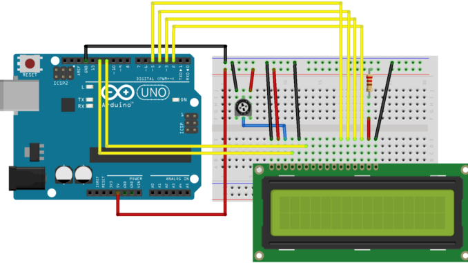
In this post on Arduino Tutorial For Beginners, We’ve already known how to make an output and control led on Arduino by programming software, in this topic we will know how to control led by hardware (button,…)
There are 2 types of input. That is external resistor and internal resistor.
First i will talk about EXTERNAL INPUT, that is pull up/down resistor. It mean i will use a resistor to make an input, below picture is how i connect.
To use Pull up/down resistor, in setup function i will setup like this
void setup()

{

pinMode(3,INPUT); //the first parameter is the Arduino’s pin which I want to receive input signal, the second is set INPUT.

}
Above is the PULL-UP diagram and how it works:
+ On the left above, when we don’t press the button, the INPUT signal is High level (5V)
+ On the left below, when we press the button, the INPUT signal is LOW level (0V)
+ On the right, i will connect Vcc(5V) to resistor, normally the resistor right here is 4k7 (Ohm) or 1k (Ohm) but with the higher voltage we need to change the resistor to make sure the input range about 3.7V-5V. And then I will connect to a pin of the button, the other pin will be connect to ground (GND). The branch between resistor and button as the diagram will be connected to pin 3(this is signal).
Example code to blink led 13 on Arduino board when press the button with PULL-UP resistor:
void setup()

{

pinMode(3,INPUT);

pinMode(13,OUTPUT);

}

void loop()

{

if(digitalRead(3) == 0)

{

while(digitalRead(3) == 0); // The program will loop here until you release the button

digitalWrite(13,HIGH);

delay(2000);

digitalWrite(13,LOW);

delay(2000);

}

}
Next is PULL-DOWN, it’s reverse with PULL-UP, below is diagram and example code
void setup()

{

pinMode(3,INPUT);

pinMode(13,OUTPUT);

}

void loop()

{

if(digitalRead(3) == 1)

{

while(digitalRead(3) == 1); // The program will loop here until you release the button

digitalWrite(13,HIGH);

delay(2000);

digitalWrite(13,LOW);

delay(2000);

}

}
Second is INTERNAL INPUT, we don’t need to use resistor with this way because Microcontroller will help us do it inside. And with Arduino’s input pin we should use voltage about 3.7V-5V to avoid burn Arduino or lost signal. Okay below is the diagram.
With INTERNAL INPUT, pin 3 when connect to button is alway HIGH level, and press is LOW level.
Example code:
void setup()

{

pinMode(3,INPUT_PULLUP); // INPUT_PULLUP when internal resistor input

pinMode(13,OUTPUT);

}

void loop()

{

if(digitalRead(3) == 0)

{

while(digitalRead(3) == 0); // The program will loop here until you release the button

digitalWrite(13,HIGH);

delay(2000);

digitalWrite(13,LOW);

delay(2000);

}

}

Leave a Reply